Working drawings are intended to enable someone other than the designer to make
a product. For this reason they have to be clear and accurate. Various conventions
and common symbols are used to help achieve this.
Four views of an object are combined into one image. The plan view (the top), the front elevation and the side elevation (the front and the sides of the object).
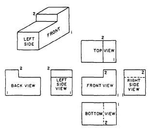 |
| All of the different view combine in diagram 2 to make an orthographic projection of the object |
 |
| This symbol shows which angle it is do not get it confused with the first angle orthographic projection |
British Standards
The overall dimensions of the object or structures are drawn in a particular way,
following a set of British Standard conventions, Briefly;
● dimension lines are placed to the side of the drawings.
● projection lines indicate the parts of the drawing the dimensions relate to.
● projection lines should not touch the drawing of the object or structure.
● dimension and projection lines should be half the thickness of the lines
of the object or structure.
Self Assembly Drawings
These are the diagrams that might come with flat pack kits from IKEA. They show all the stages in constructing an item and normally have a key. Each number references something on the diagram and gives you further instructions. These make it easier to build the product and allow easier transportation of goods and easier manufacturing as the company don't have to build it themselves. It does mean that the consumer gets the product at a cheaper price however if it constructed incorrectly this could lead to it breaking and being ineffective.
Sectional Drawings
These enlarge a small section of a drawing. It allows for possibly a mechanism to be viewed in more detail. Internal structures can be represented this way and it allows for a deeper understanding of how individual parts work.
Exploded Diagrams
These demonstrate how and object fits together. They are created;
- to scale
- accurate expression of object
- construction lines must be left on to show how it was drawn
 |
| The construction lines help demonstrate the alignments of all of the different components. |
Scale Drawings
Draw to scale means all of the dimensions of the object are the same in relation to each other However the actual size of the drawing may be bigger or smaller than the real object. This is shown as a ration.
1:2 means that every measurement in the real object is twice the size of in the drawing. For example for every 1 cm in the real object their are 2.
Plans
Often used in architectural drawings. They allow a birds eye view of say a house to be expressed. They show scale representations of the objects. This is known as a floor plan.
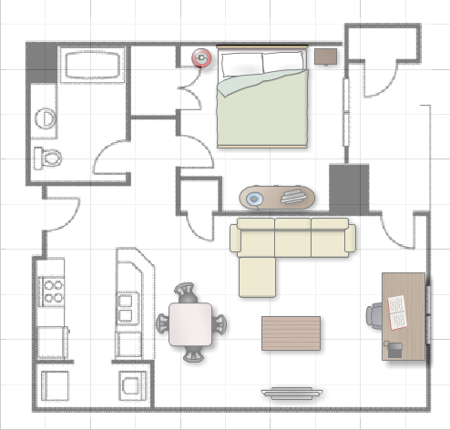 |
| all doors are shown by arc - this shows their opening space. |
No comments:
Post a Comment